Showing posts with label Knowledges. Show all posts

Saturday, May 2, 2009

Power Quality

Harmonics and electrical noise are potential problems when power electronics are utilized. As more AFD's are put into use, utilities may force users to install harmonic filtering from entering their systems. IEEE Recommended Practices and Requirements for Harmonic Control in Electrical Power Systems; IEEE Std. 519 - 1992; is written to attend to this issue. The standard has been written to limit the harmonic content introduced into the system by either the utilities or the customer.

(Note: The limits are, generally, 5% voltage distortion and 3% current distortion at the Point of Common Connection (PCC) or the point at which the utility power enters the customer plant.)
Harmonic content has attracted quite a bit of attention when discussing power quality and power electronics. Harmonics, created by the load, generally come from feedback into the line from electronic power supplies. Voltage and current harmonics tend to create alternate fields within motors and rotors, cause transformers to overheat, and interfere with other electronic systems. Odd harmonics of the fundamental frequency are generally found in power electronic systems.
In motor systems the following fundamentals of 60 Hz can be recognized:
Harm: 1st 3rd 5th 7th etc.
Rot: pos. zero neg. pos. etc.

Voltage and Current Harmonics

Positive harmonics rotate in the direction of the rotor. Other than the fundamental frequency, this type of harmonic causes heating within the stator. Negative rotating harmonics rotate against the rotor causing overheating of the rotor and reducing torque.
Zero rotating harmonics generally cause system neutrals to overheat. In the case of electronic drives, in general, the predominant harmonics are the 5th and 7th.


Read more...

Wednesday, April 29, 2009

Importance of Car Electronics and Stability of In-Car Voltage

Electrical systems in our cars are interconnected to each other. To get perfect performance you need a good and harmony electrical circuit environment. For example, if you have a old and less efficient ignition circuit in your car, you will have very poor fuel consumption, low throttle response, misfiring problem, jerking gear shift, all problems may occurred due to a single defect in another electrical problem. So to maintain optimum electrical performance in your car, we need to have a very stable voltage environment. Here comes a new electronic device - MAXI POWER SYSTEM, a multi-purpose Voltage Stabilizer with built in Battery Doctor System and Interference Reducer System. Once you use MAXI POWER SYSTEM, your car is in best control by this product, it will solve small problems that due to unstable voltage during driving. What is more wonderful, it is so easy to installed, with just a plug into cigar-lighter socket, will activate this device. Unlike other fuel saving product, by adding chemical and tablets into the fuel tank, increase the risk of car damages.

Feature
MAXI POWER SYSTEM Voltage Stabilizer has the following three systems:
• Voltage Stabilizer System
• Interference Reducer System
• Battery Doctor System

Benefits
• Fuel saving
• Better RPM response
• Increase engine torque
• Engine power up
• Optimized all electronic devices in car

Advantages
• Faster throttle response, engine power up.
• Reduce car CPU noise signal, improve CPU reaction time, improve electronic efficiency.
• Smoother gear shift on automatic car.
• Improve engine power, better acceleration response, hence improve fuel saving.
• Maximize ignition efficiency, easier engine start.
• Prolong engine and electrical device life-span.
• Easy installation, totally DIY, the first choice for ladies drivers.
• Universal for all cars and motorcycles
• Reduce noise with built in noise filter, improve sound system performance.
• Equipped with double fuse protection, for better product life and safety.
• Faster RPM response, it gives you powerful acceleration even when your car's air condition turn on to maximum load.
• Cleaner exhaust emission on HC and CO gas. So more environment friendly.
• Twelve (12) months Limited Product Warranty.


Read more...

Friday, April 17, 2009

How does a lightning arrester work?

ANSWER I:
Lightning, is a form of visible discharge of electricity between rain clouds or between a rain cloud and the earth. The electric discharge is seen in the form of a brilliant arc, sometimes several kilometres long, stretching between the discharge points. How thunderclouds become charged is not fully understood, but most thunderclouds are negatively charged at the base and positively charged at the top. However formed, the negative charge at the base of the cloud induces a positive charge on the earth beneath it, which acts as the second plate of a huge capacitor.

When the electrical potential between two clouds or between a cloud and the earth reaches a sufficiently high value (about 10,000 V per cm or about 25,000 V per in), the air becomes ionized along a narrow path and a lightning flash results.
Many meteorologists believe that this is how a negative charge is carried to the ground and the total negative charge of the surface of the Earth is maintained.
The possibility of discharge is high on tall trees and buildings rather than to ground. Buildings are protected from lightning by metallic lightning rods extending to the ground from a point above the highest part of the roof. The conductor has a pointed edge on one side and the other side is connected to a long thick copper strip which runs down the building. The lower end of the strip is properly earthed. When lightning strikes it hits the rod and current flows down through the copper strip. These rods form a low-resistance path for the lightning discharge and prevent it from travelling through the structure itself.

ANSWER II:
The lightning arrestor protects the structure from damage by intercepting flashes of lightning and transmitting their current to the ground. Since lightning strikes tends to strike the highest object in the vicinity, the rod is placed at the apex of a tall structure. It is connected to the ground by low-resistance cables. In the case of a building, the soil is used as the ground, and on a ship, water is used. A lightning rod provides a cone of protection, which has a ground radius approximately, equal to its height above the ground.


Read more...

Friday, January 30, 2009

Fans (5) - Finish

9. Fans Checklist


Read more...

Fans (4)

8. Case Studies

Blower for an Industrial Application
The operation of a centrifugal fan by damper control is energy inefficient as part of the energy supplied to the fan is lost across damper. The damper control has to be minimized by suitably optimizing the capacity of the fan to suit the requirement. One of the best methods to optimize the capacity of the fan is by reducing the rpm of the fan and operate the blower with more damper opening.


Previous Status. An air blower was operated with 30% damper opening. The blower was belt driven. The pressure required for the process was 0.0853 psi. The pressure rise of the blower was 0.1423 psi and the pressure drop across the damper was 0.0569 psi. This indicates an excess capacity/static head available in the blower.

Energy Saving Project. The rpm of the blower was reduced by 20% by suitably changing the pulley. After the reduction in rpm, the damper was operated with 60% to 70% opening. The replacement of the pulley was taken up during a non-working day. No difficulties were encountered on implementation of the project.

Financial Analysis. The reduction in rpm of the blower and minimizing the damper control resulted in reduction of power consumption by 1.2 kW. The implementation of this project resulted in an annual savings of approximately $720. The investment made was approximately $210, which was paid back in under 4 months (Confederation of Indian Industry 2001).

Read more...

Fans (3)

6. Maintenance of Fans

Typically, fans provide years of trouble-free operation with relatively minimal maintenance. However, this high reliability can lead to a false sense of security resulting in maintenance neglect and eventual failure. Due to their prominence within HVAC and other process systems (without the fan operating, the system shuts down), fans need to remain high on the maintenance activity list.

Most fan maintenance activities center on cleaning housings and fan blades, lubricating and checking seals, adjusting belts, checking bearings and structural members, and tracking vibration.

7. Diagnostic Tools

Ultrasonic analyzer – Air moving systems emit very distinct sound patterns around bearings and fan blades. In most cases, these sounds are not audible to the unaided ear or are drown-out by other equipment noises. Using an ultrasonic detector, the analyst is able to isolate the frequency of sound being emitted by the bearing or blades. Changes in these ultrasonic wave emissions are indicative of changes in equipment condition-some of these changes can be a precursor to component degradation and failure.
Vibration analyzer – Within air moving systems, there are many moving parts, most in rotational motion. These parts generate a distinct pattern and level of vibration. Using a vibration analyzer and signature analysis software, the analyst can discern the vibration amplitude of the point on the equipment being monitored. This amplitude is then compared with trended readings. Changes in these readings are indicative of changes in equipment condition.


Read more...

Fans (2)

3. Key Components

Impeller or rotor – A series of radial blades are attached to a hub. The assembly of the hub and blades is called impeller or rotor. As the impeller rotates, it creates a pressure difference and causes airflow.

Motor – It drives the blades so they may turn. It may be direct drive with the wheel mounted on the motor shaft or belt driven with the wheel mounted on its own shaft and bearings. It is important to note that fans may also be driven by other sources of motive power such as an internal combustion engine, or steam or gas turbine.
Housing – Encloses and protects the motor and impeller.

4. Safety Issues

Continuously moving fresh, uncontaminated air through a confined space is the most effective means of controlling an atmospheric hazard. Ventilation dilutes and displaces air contaminants, assures that an adequate oxygen supply is maintained during entry, and exhausts contaminants created by entry activities such as welding, oxygen-fuel cutting, or abrasive blasting (North Carolina State University 2001).

5. Cost and Energy Efficiency

In certain situations, fans can provide an effective alternative to costly air conditioning. Fans cool people by circulating or ventilating air. Circulating air speeds up the evaporation of perspiration from the skin so we feel cooler. Ventilating replaces hot, stuffy, indoor air with cooler, fresh, outdoor air. Research shows moving air with a fan has the same affect on personal comfort as lowering the temperature by over 5˚F. This happens because air movement created by the fan speeds up the rate at which our body loses heat, so we feel cooler. Opening and closing windows or doors helps the fan move indoor air outside and outdoor air inside, increasing the efficiency of the fan. When it is hot outside, close windows and doors to the outside. In the morning or evening, when outdoor air is cooler, place the fan in front of a window or door and open windows on the opposite side of the room. This draws cooler air through the living area (EPCOR 2001).
In many applications, fan control represents a significant opportunity for increased efficiency and
reduced cost. A simple and low-cost means of flow control relies on dampers, either before or after the fan. Dampers add resistance to accomplish reduced flow, while increasing pressure. This increased pressure results in increased energy use for the flow level required. Alternatives to damper flow control methods include physical reductions in fan speed though the use of belts and pulleys or variable speed controllers.


Read more...

Fans (1)

1. Introduction

The American Society of Heating, Refrigerating, and Air-Conditioning Engineers (ASHRAE) defines a fan as an “air pump that creates a pressure difference and causes airflow. The impeller does the work on the air, imparting to it both static and kinetic energy, varying proportion depending on the fan type” (ASHRAE 1992).


2. Types of Fans (Bodman and Shelton 1995)

The two general types of fans are axial-flow and centrifugal. With axial-flow fans, the air passes through the fan parallel to the drive shaft. With centrifugal fans, the air makes a right angle turn from the fan inlet to outlet.

2.1 Axial Fan
Axial-flow fans can be subdivided based on construction and performance characteristics.
Propeller fan – The basic design of propeller fans enhances maintenance to remove dust and dirt accumulations. The fan normally consists of a “flat” frame or housing for mounting, a propellershaped blade, and a drive motor. It may be direct drive with the wheel mounted on the motor shaft or belt driven with the wheel mounted on its own shaft and bearings.
• Tube-axial fans – A tube-axial fan consists of a tube-shaped housing, a propeller-shaped blade, and a drive motor. Vane-axial fans are a variation of tube-axial fans, and are similar in design and application. The major difference is that air straightening vanes are added either in front of or behind the blades. This results in a slightly more efficient fan, capable of somewhat greater static pressures and airflow rates.
2.2 Centrifugal Fans
Often called “squirrel cage” fans, centrifugal fans have an entirely different design (Figure 5). These fans operate on the principle of “throwing” air away from the blade tips. The blades can be forward curved, straight, or backward curved. Centrifugal fans with backward curved blades are generally more efficient than the other two blade configurations. This design is most often used for aeration applications where high airflow rates and high static pressures are required. Centrifugal fans with forward curved blades have somewhat lower static pressure capabilities but tend to be quieter than the other blade designs. Furnace fans typically use a forward curved blade. An advantage of the straight blade design is that with proper design it can be used to handle dirty air or convey materials.


Read more...

Tuesday, January 27, 2009

Thermography (6) - Finish

5. Case Studies


IR Diagnostics of Pump
A facility was having continual problems with some to its motor and pump combinations. Pump bearings repeatedly failed. An IR inspection confirmed that the lower thrust bearing was warmer than the other bearing in the pump.

Further investigation revealed that the motor-pump combination was designed to operate in the horizontal position. In order to save floor space, the pump was mounted vertically below the motor. As a result, the lower thrust bearing was overloaded leading to premature failure. The failures resulted in a $15,000 repair cost, not including lost production time ($30,000 per minute production loss and in excess of $600 per minute labor).

IR Diagnostics of Steam Traps
Steam trap failure detection can be difficult by other forms of detection in many hard to reach and inconvenient places. Without a good trap maintenance program, it can be expected that 15% to 60% of a facility’s traps will be failed open. At $3/1,000 lb (very conservative), a 1/4-in. orifice trap failed open will cost approximately $7,800 per year. If the system had 100 traps and 20% were failed, the loss would be in excess of $156,000. An oil refinery identified 14% of its traps were malfunctioning and realized a savings of $600,000 a year after repair.

IR Diagnostics of Roof
A state agency in the northeast operated a facility with a 360,000 square foot roof area. The roof was over 22 years old and experiencing several leaks. Cost estimates to replace the roof ranged between $2.5 and $3 million. An initial IR inspection identified 1,208 square feet of roof requiring replacement at a total cost of $20,705. The following year another IR inspection was performed that found 1,399 square feet of roof requiring replacement at a cost of $18,217. A roof IR inspection program was started and the roof surveyed each year. The survey resulted in less than 200 square feet of roof identified needing replacement in any one of the following 4 years (one year results were as low as 30 square feet). The total cost for roof repair and upkeep for the 6 years was less than $60,000.
If the facility would have been privately owned, interest on the initial $3 million at 10% would have amounted to $300,000 for the first year alone. Discounting interest on $3 million over the 5-year period, simple savings resulting from survey and repair versus initial replacement cost ($3 million to $60,000) amount to $2,940,000. This figure does not take into account interest on the $3 million, which would result in savings in excess of another $500,000 to $800,000, depending on loan interest paid.


Read more...

Thermography (5)

4. Equipment Cost/Payback


As indicated earlier, the cost of thermography equipment varies widely depending on the capabilities of the equipment. A simple spot radiometer can cost from $500 to $2,500. An IR imager without radiometric capability can range from $7,000 to $20,000. A camera with full functionality can cost from $18,000 to $65,000.

Besides the camera hardware, other program costs are involved. Computer hardware, personnel training, manpower, etc., needs to be accounted for in the budget.
Below is a listing of equipment and program needs recommended by a company recognized as a leader in the world of IR program development:
• Level I thermographic training
• Level II thermographic training
• Ongoing professional development
• IR camera and accessories
• Report software
• Laptop computer
• Color printer
• Digital visual camera
• Personal Protective Equipment (PPE) for arc flash protection

Payback can vary widely depending on the type of facility and use of the equipment. A production facility whose downtime equates to several thousands of dollars per hour can realize savings much faster than a small facility with minimal roof area, electrical distribution network, etc. On the average, a facility can expect a payback in 12 months or less. A small facility may consider using the services of an IR survey contractor. Such services are widely available and costs range from $600 to $1,200 per day. Contracted services are generally the most cost-effective approach for smaller, less maintenance-intensive facilities.


to be continued....
Read more...

Thermography (4)

3.3 Roof Thermography

Out of sight, out of mind. This old adage is particularly true when it applies to flat roof maintenance. We generally forget about the roof until it leaks on our computers, switchgear, tables, etc. Roof replacement can be very expensive and at a standard industrial complex easily run into the hundreds of thousands of dollars.

Depending on construction, length of time the roof has leaked, etc., actual building structural components can be damaged from inleakage and years of neglect that drive up repair cost further. Utilization of thermography to detect loss of a flat roof’s membrane integrity is an application that can provide substantial return by minimizing area of repair/replacement. Roof reconditioning cost can be expected to run less than half of new roof cost per square foot. Add to this the savings to be gained from reconditioning a small percentage of the total roof surface, instead of replacement of the total roof, and the savings can easily pay for roof surveys and occasional repair for the life of the building with change left over.

to be continued........


Read more...

Thermography (3)

3.2 Mechanical System Applications

Rotating equipment applications are only a small subset of the possible areas where thermography can be used in a mechanical predictive maintenance program. In addition to the ability to detect problems associated with bearing failure, alignment, balance, and looseness, thermography can be used to define many temperature profiles indicative of equipment operational faults or failure.

The following list provides a few application examples and is not all inclusive:
• Steam Systems
- Boilers
• Refractory
• Tubes
- Traps
- Valves
- Lines
• Heaters and furnaces
- Refractory inspections
- Tube restrictions
• Fluids
- Vessel levels
- Pipeline blockages
• Environmental
- Water discharge patterns
- Air discharge patterns
• Motors and rotating equipment
- Bearings
• Mechanical failure
• Improper lubrication
- Coupling and alignment problems
- Electrical connections on motors
- Air cooling of motors


to be continued..........
Read more...

Thermography (2)

3. System Applications

3.1 Electrical System Applications
The primary value of thermographic inspections of electrical systems is locating problems so that they can be diagnosed and repaired. “How hot is it?” is usually of far less importance. Once the problem is located, thermography and other test methods, as well as experience and common sense, are used to diagnose the nature of the problem.

The following list contains just a few of the possible electrical system-related survey applications:
• Transmission lines
- Splices
- Shoes/end bells
• Inductive heating problems
- Insulators

• Cracked or damaged/tracking

• Distribution lines/systems
- Splices
- Line clamps
- Disconnects
- Oil switches/breakers
- Capacitors
- Pole-mounted transformers
- Lightning arrestors
- Imbalances

• Substations
- Disconnects, cutouts, air switches
- Oil-filled switches/breakers (external and internal faults)
- Capacitors
- Transformers

• Internal problems

• Bushings

• Oil levels

• Cooling tubes

• Lightning arrestors
- Bus connections

• Generator Facilities
- Generator

• Bearings

• Brushes
• Windings
• Coolant/oil lines: blockage
- Motors
• Connections

• Bearings

• Winding/cooling patterns

• Motor Control Center

• Imbalances

• In-Plant Electrical Systems
- Switchgear
- Motor Control Center
- Bus
- Cable trays
- Batteries and charging circuits
- Power/Lighting distribution panels


Read more...

Thermography (1)

1. Introduction

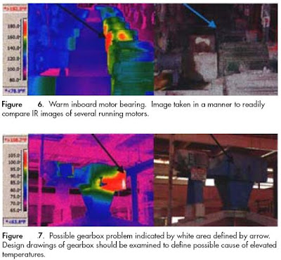
Infrared (IR) thermography can be defined as the process of generating visual images that represent variations in IR radiance of surfaces of objects. Similar to the way objects of different materials and colors absorb and reflect electromagnetic radiation in the visible light spectrum (0.4 to 0.7 microns), any object at temperatures greater than absolute zero emits IR energy (radiation) proportional to its existing temperature.

The IR radiation spectrum is generally agreed to exist between 2.0 and 15 microns. By using an instrument that contains detectors sensitive to IR electromagnetic radiation, a two-dimensional visual image reflective of the IR radiance from the surface of an object can be generated. Even though the detectors and electronics are different, the process itself is similar to that a video camera uses to detect a scene reflecting electromagnetic energy in the visible light spectrum, interpreting that information, and displaying what it detects on a liquid crystal display (LCD) screen that can then be viewed by the device operator. Because IR radiation falls outside that of visible light (the radiation spectrum to which our eyes are sensitive), it is invisible to the naked eye. An IR camera or similar device allows us to escape the visible light spectrum and view an object based on its temperature and its proportional emittance of IR radiation. How and why is this ability to detect and visualize an object’s temperature profile important in maintaining systems or components? Like all predictive maintenance technologies, IR tries to detect the presence of conditions or stressors that act to decrease a component’s useful or design life. Many of these conditions result in changes to a component’s temperature. For example, a loose or corroded electrical connection results in abnormally elevated connection temperatures due to increased electrical resistance. Before the connection is hot enough to result in equipment failure or possible fire, the patterns are easily seen through an IR imaging camera, the condition identified and corrected. Rotating equipment problems will normally result in some form of frictional change that will be seen as an increase in the component’s temperature. Faulty or complete loss of refractory material will be readily seen as a change in the components thermal profile. Loss of a roof’s membrane integrity will result in moisture that can be readily detected as differences in the roof thermal profile. These are just a few general examples of the hundreds of possible applications of this technology and how it might be used to detect problems that would otherwise go unnoticed until a component failed and resulted in excessive repair or downtime cost.


2. Types of Equipment


Many types of IR detection devices exist, varying in capability, design, and cost. In addition, simple temperature measurement devices that detect IR emissions but do not produce a visual image or IR profile are also manufactured. The following text and pictures provide an overview of each general instrument type.


Spot Radiometer (Infrared Thermometer) – Although not generally thought of in the world of thermography, IR thermometers use the same basic principles as higher end equipment to define an object’s temperature based on IR emissions. These devices do not provide any image representative of an object’s thermal profile, but rather a value representative of the temperature of the object or area of interest.

Infrared Imager - As indicated earlier, equipment capabilities, design, cost, and functionality vary greatly. Differences exist in IR detector material, operation, and design. At the fundamental level, IR detection devices can be broken down into two main groups – imagers and cameras with radiometric capability. A simple IR imager has the ability to detect an object’s IR emissions and translate this information into a visual image. It does not have the capability to analyze and quantify specific temperature values. This type of IR detection device can be of use when temperature values are unimportant and the object’s temperature profile (represented by the image) is all that is needed to define a problem. An example of such an application would be in detecting missing or inadequate insulation in a structure’s envelope. Such an application merely requires an image representative of the differences in the thermal profile due to absence of adequate insulation. Exact temperature values are unimportant.
IR cameras with full radiometric capability detect the IR emissions from an object and translate this information into a visible format as in the case of an imager. In addition, these devices have the capability to analyze the image and provide a temperature value corresponding to the area of interest. This capability is useful in applications where a temperature value is important in defining a problem or condition. For example, if an image indicated a difference between a pulley belt temperature and an ambient temperature, the belt may have worn, be the wrong size, or indicate a misalignment condition. Knowing the approximate temperature differences would be important in determining if a problem existed.


to be continued...........

Read more...

Sunday, January 25, 2009

Types of Maintenance Programs (7) - Finish

Case Study Comparison of Four Maintenance Programs (Piotrowski 2001)


Reference:
Piotrowski, J. April 2, 2001. Pro-Active Maintenance for Pumps, Archives, February 2001, Pump-Zone.com [Report online].

Read more...

Types of Maintenance Programs (6)

6. How to Initiate Reliability Centered Maintenance

The road from a purely reactive program to a RCM program is not an easy one.

The following is a list of some basic steps that will help to get moving down this path.
1. Develop a Master equipment list identifying the equipment in your facility.
2. Prioritize the listed components based on importance to process.
3. Assign components into logical groupings.
4. Determine the type and number of maintenance activities required and periodicity using:
a. Manufacturer technical manuals
b. Machinery history
c. Root cause analysis findings - Why did it fail?
d. Good engineering judgment
5. Assess the size of maintenance staff.
6. Identify tasks that may be performed by operations maintenance personnel.
7. Analyze equipment failure modes and effects.
8. Identify effective maintenance tasks or mitigation strategies.


Read more...

Types of Maintenance Programs (5)

5. Reliability Centered Maintenance

Reliability centered maintenance (RCM) magazine provides the following definition of RCM: “a process used to determine the maintenance requirements of any physical asset in its operating context.”

Basically, RCM methodology deals with some key issues not dealt with by other maintenance programs. It recognizes that all equipment in a facility is not of equal importance to either the process or facility safety. It recognizes that equipment design and operation differs and that different equipment will have a higher probability to undergo failures from different degradation mechanisms than others. It also approaches the structuring of a maintenance program recognizing that a facility does not have unlimited financial and personnel resources and that the use of both need to be prioritized and optimized. In a nutshell, RCM is a systematic approach to evaluate a facility’s equipment and resources to best mate the two and result in a high degree of facility reliability and cost-effectiveness. RCM is highly reliant on predictive maintenance but also recognizes that maintenance activities on equipment that is inexpensive and unimportant to facility reliability may best be left to a reactive maintenance approach. The following maintenance program breakdowns of continually top-performing facilities would echo the RCM approach to utilize all available maintenance approaches with the predominant methodology being predictive.
• <10%>
• 25% to 35% Preventive
• 45% to 55% Predictive.

Because RCM is so heavily weighted in utilization of predictive maintenance technologies, its program advantages and disadvantages mirror those of predictive maintenance. In addition to these advantages, RCM will allow a facility to more closely match resources to needs while improving reliability and decreasing cost.
Read more...

Types of Maintenance Programs (4)

4. Predictive Maintenance

Predictive maintenance can be defined as follows: Measurements that detect the onset of a degradation mechanism, thereby allowing causal stressors to be eliminated or controlled prior to any significant deterioration in the component physical state. Results indicate current and future functional capability.

Basically, predictive maintenance differs from preventive maintenance by basing maintenance need on the actual condition of the machine rather than on some preset schedule. You will recall that preventive maintenance is time-based. Activities such as changing lubricant are based on time, like calendar time or equipment run time. For example, most people change the oil in their vehicles every 3,000 to 5,000 miles traveled. This is effectively basing the oil change needs on equipment run time. No concern is given to the actual condition and performance capability of the oil. It is changed because it is time. This methodology would be analogous to a preventive maintenance task. If, on the other hand, the operator of the car discounted the vehicle run time and had the oil analyzed at some periodicity to determine its actual condition and lubrication properties, he/she may be able to extend the oil change until the vehicle had traveled 10,000 miles. This is the fundamental difference between predictive maintenance and preventive maintenance, whereby predictive maintenance is used to define needed maintenance task based on quantified material/equipment condition.
The advantages of predictive maintenance are many. A well-orchestrated predictive maintenance program will all but eliminate catastrophic equipment failures. We will be able to schedule maintenance activities to minimize or delete overtime cost. We will be able to minimize inventory and order parts, as required, well ahead of time to support the downstream maintenance needs. We can optimize the operation of the equipment, saving energy cost and increasing plant reliability. Past studies have estimated that a properly functioning predictive maintenance program can provide a savings of 8% to 12% over a program utilizing preventive maintenance alone. Depending on a facility’s reliance on reactive maintenance and material condition, it could easily recognize savings opportunities exceeding 30% to 40%. In fact, independent surveys indicate the following industrial average savings resultant from initiation of a functional predictive maintenance program:
• Return on investment: 10 times
• Reduction in maintenance costs: 25% to 30%
• Elimination of breakdowns: 70% to 75%
• Reduction in downtime: 35% to 45%
• Increase in production: 20% to 25%.
On the down side, to initially start into the predictive maintenance world is not inexpensive.
Much of the equipment requires cost in excess of $50,000. Training of in-plant personnel to effectively utilize predictive maintenance technologies will require considerable funding. Program development will require an understanding of predictive maintenance and a firm commitment to make the program work by all facility organizations and management.


Read more...

Types of Maintenance Programs (3)

3. Preventive Maintenance

Preventive maintenance can be defined as follows: Actions performed on a time- or machine-run-based schedule that detect, preclude, or mitigate degradation of a component or system with the aim of sustaining or extending its useful life through controlling degradation to an acceptable level.

The U.S. Navy pioneered preventive maintenance as a means to increase the reliability of their vessels. By simply expending the necessary resources to conduct maintenance activities intended by the equipment designer, equipment life is extended and its reliability is increased.
In addition to an increase in reliability, dollars are saved over that of a program just using reactive maintenance. Studies indicate that this savings can amount to as much as 12% to 18% on the average. Depending on the facilities current maintenance practices, present equipment reliability, and facility downtime, there is little doubt that many facilities purely reliant on reactive maintenance could save much more than 18% by instituting a proper preventive maintenance program.
While preventive maintenance is not the optimum maintenance program, it does have several advantages over that of a purely reactive program. By performing the preventive maintenance as the equipment designer envisioned, we will extend the life of the equipment closer to design. This translates into dollar savings. Preventive maintenance (lubrication, filter change, etc.) will generally run the equipment more efficiently resulting in dollar savings. While we will not prevent equipment catastrophic failures, we will decrease the number of failures. Minimizing failures translate into maintenance and capitol cost savings.


Read more...

Types of Maintenance Programs (2)

2. Reactive Maintenance

Reactive maintenance is basically the “run it till it breaks” maintenance mode. No actions or efforts are taken to maintain the equipment as the designer originally intended to ensure design life is reached.

Studies as recent as the winter of 2000 indicate this is still the predominant mode of maintenance in the United States. The referenced study breaks down the average maintenance program as follows:
• >55% Reactive
• 31% Preventive
• 12% Predictive
• 2% Other.
Note that more than 55% of maintenance resources and activities of an average facility are still reactive.
Advantages to reactive maintenance can be viewed as a double-edged sword. If we are dealing with new equipment, we can expect minimal incidents of failure. If our maintenance program is purely reactive, we will not expend manpower dollars or incur capitol cost until something breaks.
Since we do not see any associated maintenance cost, we could view this period as saving money. The downside is reality. In reality, during the time we believe we are saving maintenance and capitol cost, we are really spending more dollars than we would have under a different maintenance approach. We are spending more dollars associated with capitol cost because, while waiting for the equipment to break, we are shortening the life of the equipment resulting in more frequent replacement. We may incur cost upon failure of the primary device associated with its failure causing the failure of a secondary device. This is an increased cost we would not have experienced if our maintenance program was more proactive. Our labor cost associated with repair will probably be higher than normal because the failure will most likely require more extensive repairs than would have been required if the piece of equipment had not been run to failure. Chances are the piece of equipment will fail during off hours or close to the end of the normal workday. If it is a critical piece of equipment that needs to be back on-line quickly, we will have to pay maintenance overtime cost. Since we expect to run equipment to failure, we will require a large material inventory of repair parts. This is a cost we could minimize under a different maintenance strategy.


Read more...

Search here:

Translate to :

Official Website

Name:*
Email:*
Tel / HP:
Subject:*
Message:*
Verification No.:*
contact form faq

Our Services :

- Machine troubleshooting
- Automation, mechanical, instrumentation, electrical design, installation & commisioning
- Machine design, machine installation/relocation
- PLC software, programming, installation & commisioning
- Instruction manual, troubleshooting guide, technical guide etc
- Panel maker (distribution, control desk, capacitor bank, PLC, starter unit, inverter unit etc)
- Inverter design, installation & commisioning
- Motor
- Energy saving solutions
- Etc