Showing posts with label PLC. Show all posts

Thursday, January 22, 2009

Introduction to PLC Programming and Implementation (14)

SIMPLE START/STOP MOTOR CIRCUIT

Figure 25 shows the wiring diagram for a three-phase motor and its corresponding three-wire control circuit, where the auxiliary contacts of the starter seal the start push button.

To convert this circuit into a PLC program, first determine which control devices will be part of the PLC I/O system; these are the circled items in Figure 26. In this circuit, the start and stop push buttons (inputs) and the starter coil (output) will be part of the PLC system. The starter coil’s auxiliary contacts will not be part of the system because an internal will be used to seal the coil, resulting in less wiring and fewer connections.


Table 11 shows the I/O address assignment, which uses the same addressing scheme as the circuit diagram (i.e., inputs: addresses 000 and 001, output: address 030).


To program the PLC, the devices must be programmed in the same logic sequence as they are in the hardwired circuit (see Figure 27). Therefore, the stop push button will be programmed as an examine-ON instruction (a normally open PLC contact) in series with the start push button, which is also programmed as an examine-ON instruction. This circuit will drive output 030, which controls the starter. If the start push button is pressed, output 030 will turn ON, sealing the start push button and turning the motor ON through the starter. If the stop push button is pressed, the motor will turn OFF. Note that the stop push button is wired as normally closed to the input module. Also, the starter coil’s overloads are wired in series with the coil. In a PLC wiring diagram, the PLC is connected to power lines L1 and L2 (see Figure 28). The field inputs are connected to L1 on one side and to the module on the other. The common, or return, connection from the input module goes to L2. The output module receives its power for switching the load from L1. Output terminal 030 is connected in series with the starter coil and its overloads, which go to L2. The output module also directly connects to L2 for proper operation. Note that, in the motor control circuit’s wiring diagram (see Figure 29), the PLC output module is wired directly to the starter coil.


Although the three-phase motor has a three-wire control circuit, its corresponding PLC control circuit has only two wires. This two-wire configuration is similar to a three-wire configuration because it provides low-voltage release; however, it does not provide low-voltage protection. Referring to Figure 29, the starter’s seal-in contacts (labeled as 3— —2) are not used and are shown as unconnected. If the motor is running and the overloads open, the motor will stop, but the circuit will still be ON. Once the overloads cool off and the overload contacts close, the motor will start again immediately. Depending on the application, this situation may not be desirable. For example, someone may be troubleshooting the motor stoppage and the motor may suddenly restart. Making the auxiliary contact an input and using its address to seal the start push button can avoid this situation by making the two-wire circuit act as a three-wire circuit (see Figure 30). In this configuration, if the overloads open while the motor is running, the coil will turn off and their auxiliary contacts will break the circuit in the PLC.






Read more...

Introduction to PLC Programming and Implementation (13)

SIMPLE RELAY REPLACEMENT

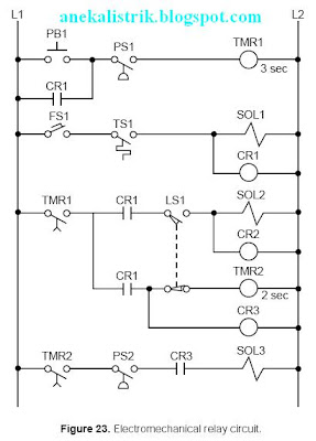
This relay replacement example involves the PLC implementation of the electromechanical circuit shown in Figure 23.

The hardware timer TMR1 requires instantaneous contacts in the first rung, which are used to latch the rung. If the instantaneous TMR1 contacts are implemented using a PLC timedelay contact, then PB1 must be pushed for the timer’s required time preset to latch the rung. This instantaneous contact will be implemented by trapping the timer with an internal output.

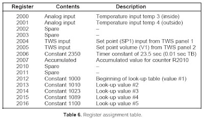
Tables 8 and 9 show the I/O address and internal output assignments for the electromechanical circuit’s real I/O. Table 10 presents the register assignment table. Note that internals do not replace control relays CR1 and CR2 since the output addresses 030 and 031 corresponding to solenoids SOL1 and SOL2 are available. Therefore, addresses 030 and 031 can replace the CR1 and CR2 contacts, respectively, everywhere they occur in the program. The normally open contact LS1 connects limit switch LS1 to the PLC input interface; and the normally open LS1 reference, programmed with an examine-OFF instruction, implements the normally closed LS1 in the program. Figure 24 illustrates the PLC program coding solution.


Read more...

Introduction to PLC Programming and Implementation (12)

5. DISCRETE I/O CONTROL PROGRAMMING

In this section, we will present several programming examples that illustrate the modernization of relay systems. We will also present examples relating to new PLC control implementations. These examples will deal primarily with discrete controls. The next section will explain more about analog I/O interaction and programming.

CONTROL PROGRAMMING AND PLC DESCRIPTIONS

Modernization applications involve the transfer of a machine or process’s control from conventional relay logic to a programmable controller. Conventional hardwired relay panels, which house the control logic, usually present maintenance problems, such as contact chatter, contact welding, and other electromechanical problems. Switching to a PLC can improve the performance of the machine, as well as optimize its control. The machine’s “new” programmable controller program is actually based on the instructions and control requirements of the original hardwired system. Throughout this section, we will use the example of a midsized PLC capable of handling up to 512 I/O points (000 to 777 octal) to explain how to implement and configure a PLC program. The I/O structure of the controller has 4 I/O points per module. The PLC has eight racks (0 through 7), each one with eight slots, or groups, where modules can be inserted. Figure 22 illustrates this configuration.


The PLC can accept four-channel analog input modules, which can be placed in any slot location. When analog I/O modules are used, discrete I/O cannot be used in the same slot. The PLC can also accept multiplexed register I/O. These multiplexed modules require two slot positions and provide the enable (select) lines for the I/O devices.
Addresses 000 through 777 octal represent input and output device connections mapped to the I/O table. The first digit of the address represents the rack number, the second digit represents the slot, and the third digit specifies the terminal connection in the slot. The PLC detects whether the slot holds an input or an output.

Point addresses 1000(8) to 2777(8) may be used for internal outputs, and register storage starts at register 3000(8) and ends at register 4777(8). Two types of timer and counter formats can be used—ladder format and block format—but all timers require an internal output to specify the ON-delay output. Ladder format timers place a “T” in front of the internal output address, while block format timers specify the internal output address in the block’s output coil. Throughout the examples presented in this section and the next, we will use addresses 000(8) through 027(8) for discrete inputs and addresses 030(8) through 047(8) for discrete outputs. Analog I/O will be placed in the last slot of the master rack (0) whenever possible. During the development of these examples, you will discover that sometimes the assignment of internals and registers is performed parallel to the programming stages.


Read more...

Introduction to PLC Programming and Implementation (11)

PROGRAM CODING/TRANSLATION

Program coding is the process of translating a logic or relay diagram into PLC ladder program form. This ladder program, which is stored in the application memory, is the actual logic that will implement the control of the machine or process.

Ease of program coding is directly related to how orderly the previous stages (control task definition, I/O assignment, etc.) have been done. Figure 21 shows a sample program code generated from logic gates and electromechanical relay diagrams (internal coil 1000 replaces the control relay). Note that the coding is a PLC representation of the logic, whether it is a new application or a modernization. The next sections examine this coding process closer and present several programming examples.


to be continued.............
Read more...

Introduction to PLC Programming and Implementation (10)


EXAMPLE 3
Highlight the sections of the circuit in Figure 15 that will be under the control of a PLC MCR. What additional measures must be taken to include or bypass other hardwired circuits within the MCR fence?

SOLUTION
Figure 16 highlights the circuits that must be fenced under the MCR instruction. Note that solenoid SOL1 and part of its driving logic are not included in the MCR fencing because SOL1, CR3, and TDR1 can also be turned ON by logic prior to the MCR fence (see Figure 17).

For the MCR fence to be properly programmed, the PLC program must include two internal control relays that take SOL1 out of the fence. Figure 18 illustrates the fenced circuit with the additional internals (CR1000 and CR1001). Note that the instructions in this diagram have the same names as in the hardwired circuit. The solenoid SOL1 will be outside of the MCR fence because it can be turned ON by either the outside logic (highlighted section in Figure 17) or the logic inside the MCR fence (highlighted section in Figure 18).


Bidirectional Power Flow. The circuit in Figure 19 illustrates another condition that can cause programming problems: the possibility of bidirectional power flow through the normally closed CR4 contact in line 8. To solve the bidirectional flow problem, the programmer must know whether or not CR4 influences the two output rungs to which it is connected. These rungs are the CR3 control relay output and the solenoid SOL1 output (rungs 7 and 9, respectively). Figure 19 illustrates the two paths that can occur in the hardwired circuit. PLCs only allow forward paths; therefore, if a reverse path is necessary for this circuit’s logic, the CR4 contact must be included in the logic driving the CR3 output (see Figure 9b).


Instantaneous Timer Contacts. The electromechanical circuit shown in Figure 15 specifies an instantaneous timer contact (the normally open TDR1 contact in line 10). This type of contact, however, is usually unavailable in PLCs. To implement an instantaneous timer contact (i.e., a contact that closes or opens once the timer is enabled), the programmer must use an internal output to trap the timer, then use the internal’s contact as an instantaneous contact to drive the timer’s logic.
In the electromechanical circuit in Figure 20a, if PB1 and LS1 both close, the timer will start timing and the instantaneous contact (TMR1-1) will close, thus sealing PB1. If PB1 is released (OFF), the timer will continue to time because the circuit is sealed. Figure 20b illustrates the technique for trapping a timer. In this PLC program, an internal output traps the instantaneous contact from the circuit’s electromechanical timer. Thus, the contacts from this internal drive the timer. If a trap does not exist, the timer will start timing when PB1 and LS1 both close, but will stop timing as soon as PB1 is released.


Complicated Logic Rungs. When a logic rung is very confusing, the best programming procedure is to isolate it from the other rungs. Then, reconstruct all of the possible logic paths from right to left, starting at the output and ending at the beginning of the rung. If a section of a rung, like the one discussed in Example 3, directly connects or interacts with another rung, it may be easier to create an internal output at the point where the two rungs cross. Then, use the internal output to drive the rest of the logic. For the circuit shown in Figure 15, this cross point is in line 9 at the normally closed contact CR4 between normally open LS1 and normally closed CR3.


Read more...

Introduction to PLC Programming and Implementation (9)

SPECIAL INPUT DEVICE PROGRAMMING

Some PLC circuits and input connections require special programming. One example is the programming of normally closed input devices. Remember that the programming of a device is closely related to how that device should behave in the control program.

Normally Closed Devices. An input device that is wired as a normally open input can be programmed to act as either a normally open or a normally closed device. The same rule applies for normally closed inputs. Generally, if a device is wired as a normally closed input and it must act as a normally closed input, its reference address is programmed as normally open. As the following example illustrates, however, a normally closed device in a hardwired circuit is programmed as normally closed when it is replaced in the PLC control program. Since it is not referenced as an input, the program does not evaluate the device as a real input.

EXAMPLE 2
For the circuit in Figure 11, draw the PLC ladder program and create an I/O address assignment table. For inputs, use addresses 10(8) through 47(8). Start outputs at address 50(8) and internals at address 100(8).


SOLUTION
Figure 12 shows the equivalent PLC ladder diagram for the circuit in Figure 11. Table 7 shows the I/O address assignment table for this example. The normally closed contact (CR10) is programmed as normally closed because internal coil 100 references it and requires it to operate as a normally closed contact.


Master Control Relays. Another circuit the programmer should be aware of is a master control relay (MCR). In electromechanical circuit diagrams, an MCR coil controls several rungs in a circuit by switching ON or OFF the power to those rungs. In a hardwired circuit, there is no definite end to an MCR except when the circuit is followed all the way through. For example, in Figure13, the MCR output in line 1 controls the power to the hardwired elements from line 3, where the MCR contact is located, to the last element in line 51. If the master control relay is ON, power will flow to these rungs (lines 4 through 51). If the master control relay is OFF, power will not flow and these devices will not implement the control action. This configuration is equivalent to a hardwired subprogram or subroutine—if the MCR is ON, the rungs are executed; if it is OFF, the rungs are not executed. At line 2 in the circuit, power branches to other circuits that are not affected by the MCR’s action. These circuits are the regular hardwired program.
During the translation from a hardwired ladder circuit to PLC symbology, the programmer must place an END MCR instruction after the last rung the MCR should control. Figure14 illustrates the placement of the MCR instruction for the circuit in Figure 13. To provide proper fencing for the program’s MCR control section, internal output coil 1000, labeled CR1 (line 1 of PLC program), was inserted so that PL1 would not be inside the fenced MCR area. This is the way the hardwired circuit operates.

The END1 instruction ends the MCR fence. The instructions corresponding to the hardwired circuits that branch from line 2 in the electromechanical diagram of Figure 13 are located after the END1 instruction. Figure15 illustrates a partial ladder rung of a more elaborate circuit with this type of MCR condition. The corresponding PLC program should have an END MCR after the rung containing the PL3 output.


Read more...

Introduction to PLC Programming and Implementation (8)

REGISTER ADDRESS ASSIGNMENT
The assignment of addresses to the registers used in the control program is another important aspect of PLC organization. The easiest way to assign registers is to list all of the available PLC registers. Then, as they are used, describe each register’s contents, description, and function in a register assignment table. Table 6 shows a register assignment table for the first 15 registers in a PLC system, ranging from address 2000(8) to address 2016(8)


ELEMENTS TO LEAVE HARDWIRED

During the assignment of inputs and outputs, the user should decide which devices will not be wired to the controller. These elements will remain part of the electromechanical control logic. These elements usually include devices that are not frequently switched off after start, such as compressors and hydraulic pumps. Components like emergency stops and master start push buttons should also remain hardwired, principally for safety purposes. This way, if the controller is faulty and an emergency occurs, the user can shut down the system without PLC intervention.
Figure 10 provides an example of system components that are typically left hardwired. Note that the normally open PLC Fault Contact 1 (or watchdog timer contact) is wired in series with other emergency conditions. This contact stays closed when the controller is operating correctly, but opens when a fault occurs. The system designer can also use this contact if an emergency occurs to disable the PLC system’s operation. PLC fault contacts are safety contacts that are available to the user when implementing or enhancing a safety circuit. When a PLC is operating correctly, the normally open fault contact closes and the normally closed one opens when the PLC is first turned on. As shown in Figure 10, these contacts are connected in series with the hardwired circuit, so that if the PLC fails during standard operation, the normally open contacts will open. This will shut down the hardwired circuit at the point where the PLC becomes the controlling element. This circuit also uses a safety control relay (SCR) to control power to the rest of the control components. The normally closed fault contacts are used to indicate an alarm condition.


In the diagram shown in Figure 10, an emergency situation (including a PLC malfunction) will remove power (L1) to the I/O modules. The turning OFF of the safety control relay (SCR) will open the SCR contact, stopping the flow of power to the system. Furthermore, the normally closed PLC fault contact (PLC Fault Contact 2) in the hardwired section will alert personnel of a system failure due to a PLC malfunction. The designer should implement this type of alarm in the main PLC rack, as well as in each remote I/O rack location, since remote systems also have fault contacts incorporated into the remote controllers. This allows subsystem failures to be signaled promptly, so that the problem can be fixed without endangering personnel.

Read more...

Introduction to PLC Programming and Implementation (7)

EXAMPLE 1
For the circuit shown in Figure 7, (a) identify the real inputs and outputs by circling each, (b) assign the I/O addresses, (c) assign the internal addresses (if required), and (d) draw the I/O connection diagram.

Assume that the PLC used has a modularity of 8 points per module. Each rack has 8 module slots, and the master rack is number 0. Inputs and outputs can have any address as long as the correct module is used. The PLC determines whether an input or output module is connected in a slot. The number system is octal, and internals start at address 10008.


SOLUTION
(a) Figure 8 shows the circled real input and output connections. Note that temperature switch TS3 is circled twice even though it is only one device. In the address assignment, only one of them is referenced, and only one of them is wired to an input module.
(b) Table 4 illustrates the assignment of inputs and outputs. It assigns all inputs and all outputs, leaving spare I/O locations for future use.


(c) Table 5 presents the output assignments, including a description of each internal. Note that control relay CR2 is not assigned as an internal since it is the same as the output rung corresponding to PL1. When the control program is implemented, every contact associated with CR2 will be replaced by contacts with address 020 (the address of PL1).


(d) Figure 9 illustrates the I/O connection diagram for the circuit in Figure 7. This diagram is based on the I/O assignment from part (b). Note that only one of the temperature switches, the normally open TS3 switch, is a connected input. The logic programming of each switch should be based on a normally open condition.


Read more...

Introduction to PLC Programming and Implementation (6)

CONFIGURING THE PLC SYSTEM

PLC configuration should be considered during flowcharting and logic sequencing. The PLC’s configuration defines which I/O modules will be used with which types of I/O signals, as well as where the modules will be located in the local or remote rack enclosures. The modules’ locations determine the I/O addresses that will be used in the control program.

During system configuration, the user should consider the following: possible future expansions; special I/O modules, such as fast-response or wire fault inputs; and the placement of interfaces within a rack (all AC I/O together, all DC and low-level analog I/O together, etc.). Consideration of these details, along with system configuration documentation, will result in a better system design.

REAL AND INTERNAL I/O ASSIGNMENT

The assignment of inputs and outputs is one of the most important procedures that occurs during the programming organization and implementation stages. The I/O assignment table documents and organizes what has been done thus far. It indicates which PLC inputs are connected to which input devices and which PLC outputs drive which output devices. The assignment of internals, including timers, counters, and MCRs, also takes place here.
These assignments are the actual contact and coil representations that are used in the ladder diagram program. In applications where electromechanical relay diagrams are available (e.g., modernization of a machine or process), identification of real I/O can be done by circling the devices and then assigning them I/O addresses (see Example 1).
Table 2 shows an I/O address assignment table for real inputs and outputs, while Table 3 shows an I/O address assignment table for internals. These assignments can be extracted from the logic gate diagrams or ladder symbols that were used to describe the logic sequences. They can also come from the circled elements on an electromechanical diagram. The numbers used for the I/O addresses depend on the PLC model used. These addresses can be represented in octal, decimal, or hexadecimal. The description section of the table specifies the field devices that correspond to each address.


The table of address assignments should closely follow the input/output connection diagram (see Figure 6). Although industry standards for I/O representations vary among users, inputs and outputs are typically represented by squares and diamonds, respectively. The I/O connection diagram forms part of the documentation package.

During the I/O assignment, the user should group associated inputs and outputs. This grouping will allow the monitoring and manipulation of a group of I/O simultaneously. For instance, if 16 motors will be started sequentially, they should be grouped together, so that monitoring the I/O registers associated with the 16 grouped I/O points will reveal the motors’ starting sequence. Due to the modularity of an I/O system, all the inputs and all the outputs should be assigned at the same time. This practice will prevent the assignment of an input address to an output module and vice versa.


Read more...

Introduction to PLC Programming and Implementation (5)

CREATING FLOWCHARTS AND OUTPUT SEQUENCES

Flowcharting is a technique often used when planning a program after a written description has been developed. A flowchart is a pictorial representation that records, analyzes, and communicates information, as well as describes the operational process in a sequential manner. Figure 2 illustrates a simple flowchart. Each step in the chart performs an operation, whether it is an input/output, decision, or data process.

In a flowchart, broad concepts and minor details, along with their relationship to each other, are readily apparent. Sequences and relationships that are hard to extract from general descriptions also become obvious when expressed through a flowchart. Even the flowchart symbols themselves have specific meanings, which aid in the interpretation of the solution algorithm. Figure 3 illustrates the most common flowchart symbols and their meanings.
The main flowchart itself should not be long and complex; instead, it should point out the major functions to be performed (e.g., compute engineering units from analog input counts). Several smaller flowcharts can be used to further describe the functions specified in the main flowchart.
Once the flowchart is completed, the user can employ either logic gates or contact symbology to implement the logic sequences. Logic gates implement a logical output sequence given specific real and/or internal input conditions,while PLC contact symbology directly implements the logic necessary to program an output rung.


Figure 4 illustrates both of these programming methods. Users should employ whichever method they feel most comfortable with or, perhaps, a combination of both (see Figure 5). Logic gate diagrams, however, may be more appropriate in controllers that use Boolean instruction sets. Inputs and outputs marked with an X on a logic gate diagram, as in Figure 4b, represent real I/O in the system. If no mark is present, an I/O point is an internal. The labels used for actual input signals can be either the actual device names (e.g., LS1, PB10, AUTO, etc.) or symbolic letters and numbers that are associated with each of the field elements. During this stage, the user should prepare a short description of the logic sequence.


Read more...

Wednesday, January 21, 2009

Introduction to PLC Programming and Implementation (4)

4. PROGRAM ORGANIZATION AND IMPLEMENTATION

Organization is a key word when programming and implementing a control solution. The larger the project, the more organization is needed, especially when a group of people is involved.

In addition to organization, a successful control solution also depends on the ability to implement it. The programmer must understand the PLC control task and controlled devices, choose the correct equipment for the job (hardware and software), and understand the PLC system. Once these preliminary details are understood, the programmer can begin sketching the control program solution. The work performed during this time forms an important part of the system or project documentation. Documenting a system once it is installed and working is difficult, especially if you do not remember how you got it to work in the first place. Therefore, documenting the system throughout its development will pay off in the end.


Read more...

Introduction to PLC Programming and Implementation (3)

3. IMPLEMENTATION GUIDELINES

A programmable controller is a powerful machine, but it can only do what it is told to do. It receives all of its directions from the control program, the set of instructions or solution algorithms created by the programmer. Therefore, the success of a PLC control program depends on how organized the user is. There are many ways to approach a problem; but if the application is approached in a systematic manner, the probability of mistakes is less.

The techniques used to implement the control program vary according to the programmer. Nevertheless, the programmer should follow certain guidelines. Table1 lists programming guidelines for new applications and modernizations. New applications are new systems, while modernizations are upgraded existing control systems that have functioned previously without a
PLC (i.e., through electromechanical control or individual, analog, loop controllers).


As mentioned previously, understanding the process or machine operation is the first step in a systematic approach to solving the control problem. For new applications, the strategy should follow the problem definition. Reviewing strategies for new applications, as well as revising the actual method of control for a modernization project, will help detect errors that were introduced
during the planning stages.
The programming stage reveals the difference between new and modernization projects. In a modernization project, the user already understands the operation of the machine or process, along with the control task. An existing relay ladder diagram, like the one shown in Figure1, usually defines the sequence of events in the control program. This ladder diagram can be almost directly translated into PLC ladder diagrams.
New applications usually begin with specifications given to the person who will design and install the control system. The designer translates these specifications into a written description that explains the possible control strategies. The written explanation should be simple to avoid confusion. The designer then uses this explanation to develop the control program.


Read more...

Introduction to PLC Programming and Implementation (2)

2. CONTROL STRATEGY

After the control task has been defined, the planning of its solution can begin. This procedure commonly involves determining a control strategy, the sequence of steps that must occur within the program to produce the desired output control. This part of the program development is known as the development of an algorithm. The term algorithm may be new or strange to some readers, but it need not be.

Each of us follows algorithms to accomplish certain tasks in our daily lives. The procedure that a person follows to go from home to either school or work is an algorithm—the person exits the house, gets into the car, starts the engine, and so on. In the last of a finite number of steps, he or she reaches the destination.
The PLC strategy implementation for a control task closely follows the development of an algorithm. The user must implement the control from a given set of basic instructions and produce the solution in a finite number of steps. If developing an algorithm to solve the problem becomes difficult, he or she may need to return to the control task definition to redefine the problem. For example, we cannot explain how to get from where we are to Bullfrog County, Nevada unless we know both where we are and where Bullfrog County is. As part of the problem definition, we need to know if a particular method of transportation is required. If there is a time constraint, we need to know that too. We cannot develop a control strategy until we have all of this problem definition information.
The fundamental rule for defining the program strategy is think first, program later. Consider alternative approaches to solving the problem and allow time to polish the solution algorithm before trying to program the control function. Adopting this philosophy will shorten programming time, reduce debugging time, accelerate start-up, and focus attention where it is needed—on design when designing and on programming when programming.
Strategy formulation challenges the system designer, regardless of whether it is a new application or the modernization of an existing process. In either case, the designer must review the sequence of events and optimize control through the addition or deletion of steps. This requires a knowledge of the PLC-controlled field devices, as well as input and output considerations.


Read more...

Introduction to PLC Programming and Implementation (1)

1. CONTROL TASK DEFINITION

A user should begin the problem-solving process by defining the control task, that is, determining what needs to be done. This information provides the foundation for the control program. To help minimize errors, the control task should be defined by those who are familiar with the operation of the machine or process. Proper definition of the task is directly related to the success of the control program.

Control task definition occurs at many levels. All of the departments involved must work together to determine what inputs are required, so that everyone understands the purpose and scope of the project. For example, if a project involves the automation of a manufacturing plant in which materials will be retrieved from the warehouse and sent to the automatic packaging area, personnel from both the warehouse and packaging areas must collaborate with the engineering group during the system definition.
Management should also be involved if the project requires data reporting. If the control task is currently done manually or through relay logic, the user should review the steps of the manual procedure to determine what improvements, if any, can be made. Although relay logic can be directly implemented in a PLC, the procedure should be redesigned, when possible, to meet current project needs and to capitalize on the capabilities of programmable controllers.


Read more...

Tuesday, December 30, 2008

PLCs and Fuzzy Logic (11) - Finish

Rule Decision Making and Outcome Determination

The easiest way to formulate the rules for a fuzzy logic controller is to first write them as IF…THEN statements that describe how the inputs affect the outcome.

Some fuzzy controllers are capable of handling two outputs at the same time, thus allowing two rules to be combined. For example, the rules:

IF A = PS AND B = NS THEN C = ZR
IF A = PS AND B = NS THEN D = NS

can be combined into one rule:

IF A = PS AND B = NS THEN C = ZR and D = NS

This rule gives two outcomes, thus invoking two defuzzification processes, one for each controlling output. It is easiest, however, to create each rule individually (with only one outcome) and then combine them later.
A fuzzy logic controller may or may not provide a choice of output membership function shapes (L, P, S, or Z). Moreover, it may or may not provide a choice about whether the functions are continuous or noncontinuous. However, before defuzzification occurs, all fuzzy controllers add the outcomes based on the appropriate rule logic. If the rule contains a logical AND function, the controller will select the lowest output value; if the rule contains an OR function, the controller will select the highest output value.
If an application requires a highly accurate or smooth output, the rules should be designed so that an input condition triggers two or more rules. To do this, either the input membership functions must overlap or two input conditions must influence the same output.


Defuzzification

During the implementation of a fuzzy logic system, the system designer may be required to choose a defuzzification method, especially if the output membership function is noncontinuous.
Defuzzification methods include the center of gravity (centroid), the left-most maximum, and the right-most maximum. If the selected defuzzification method is the center of gravity approach, the triggering rules must be arranged so that at least one rule is triggered at all times.
Thus, there must always be an output from a rule. The controller will generate an error if there is no output due to a gap in input condition coverage (see Figure 14).

CONCLUSION

Fuzzy logic processing is a three-step procedure consisting of fuzzification, fuzzy processing, and defuzzification. Using this three-step process, a fuzzy controller can take vague nondiscrete input
data and convert it into a specific output. This conversion process depends on the membership functions and rules established by the system designer during system implementation. When used correctly, fuzzy logic controllers can improve the performance of PLC systems that control both closed-loop and open-loop systems. They can also lead to the automation of tasks that previously required human intervention. Together, PLCs and fuzzy logic technology form a powerful tool for enhancing complex system automation.
If this article is useful for you, please click our sponsors

Read more...

PLCs and Fuzzy Logic (10)

Input/Output Determination
Once the fuzzy system configuration has been established, the next step is to determine which inputs and outputs will be used in the fuzzy logic controller. The input conditions, or fuzzy input variables, must be able to be expressed by IF…THEN statements.

That is, the input conditions to the fuzzy controller must be able to trigger conditional rules, meaning that they specify one or more output conditions. Inputs should be selected according to the process situations they describe. These variables should relate to similar process elements. If two inputs have little to do with each other, they will generate an outcome that is less effective than the outcome generated by two inputs that deal with the same element. For example, in a temperature-regulating batching operation, the batch temperature and tank jacket temperature both relate to the regulation of the steam valve output. By analyzing these two inputs together, a fuzzy controller can make a precise decision about how much to adjust the steam valve. An analysis of two unrelated inputs, such as batch temperature and liquid level, would not provide such an informed decision.

Fuzzy Inference Engine
The selection of the fuzzy inference engine encompasses the determination of how the fuzzification process will take place (e.g., the number and form of membership function, etc.), how the rules determine an outcome, and how the fuzzy controller implements defuzzification.

Fuzzification
The fuzzification process, which utilizes the membership functions defined by the user, assigns a grade to each fuzzy input received. This grade determines the level of outcome that will be triggered. Therefore, the shape of a fuzzy set’s membership functions is important, since this shape determines the input signals’ grades, which are mapped to the output membership function.
Some fuzzy controllers allow the user to choose the shape of the membership functions by trial and error, while others have predefined membership function shapes. When using trial and error to determine the function shapes in a closed-loop fuzzy control system, the input membership functions should begin with overlapped L-shaped labels (see Figure 12). This ensures smoother control for the first trial due to the coverage provided by the L shape and the overlapping at the minimum and maximum points, which creates a balance (i.e., when one label grade is 1, the other is 0). The number of labels, or membership functions, that will form the fuzzy set is also an important part of the system design. For example, if a fuzzy set has five labels covering the same input data range as a three-label fuzzy set, the one with five labels will provide more fine-tuned control, especially if the output membership function also has five labels.

Although membership functions do not have to be symmetrical, asymmetrical fuzzy sets should be carefully designed to ensure that they describe the fuzzy variable input properly. In Figure 13a, the inner membership functions provide more sensitivity near the zero label (from NS to PS) than at the NL and PL labels (from NL to NS and from PS to PL). Asymmetrical membership functions are typically used in open-loop system applications.

Sometimes, a membership function in a fuzzy set may not provide any sensitivity between two labels. As illustrated in Figure 13b, the flat sections of the membership functions do not influence
neighboring functions or the output. Therefore, the output will not change if the input variable falls in these regions.

to be continued................
If this article is useful for you, please help us with click our sponsor
Read more...

PLCs and Fuzzy Logic (9)

GUIDELINES FOR CONTROLLING COMPLEX SYSTEMS


All fuzzy logic applications are different. However, certain design guidelines apply to all fuzzy logic systems. These guidelines provide the basic elements for the successful implementation of a
fuzzy logic control system.

They include:
• control objectives
• control system configuration
• input/output determination
• fuzzy inference engine design

Control Objectives
Fuzzy logic can be applied to virtually any type of control system, but it is especially suited for applications that rely heavily on human intuition and experience. The primary objective of applying fuzzy logic to an existing process is to improve the overall process and to automate tasks that previously required human judgment. In a new system, the primary objective of using fuzzy logic is to implement control that cannot be implemented using standard control methods. A system designer should not use fuzzy logic control just because it is available. Rather, the designer should use it because it will enhance the system. Otherwise, the outcome may not be enhanced; it may just become confusing.
Typical applications of fuzzy logic involve batching systems and temperature control loops, where process control involves “tweaking” the output based on judgments about input conditions. For example, a temperature control loop application typically requires a knowledgeable operator who can regulate the control element based on decisions such as “if the temperature is a little high but all other inputs are OK, then turn the steam valve a little clockwise.” This rationale lends itself to fuzzy logic control.

Control System Configuration
The control objective leads to the selection of the fuzzy logic system configuration. There are several types of fuzzy configurations. Fuzzy logic does not have to be applied only in dedicated fuzzy control applications. It can also be used as a complementary system that supports another more conventional control method, such as a PID control loop. When used in this manner, the system is said to be a conventional fuzzy hybrid control system.

to be continued..................
If this article is useful for you, please help us with click our sponsors.
Read more...

PLCs and Fuzzy Logic (8)

Membership Functions and Rule Creation
To provide enhanced resolution and accuracy, this system uses five–membership function (fivelabel) fuzzy sets for the two inputs and a seven–membership function fuzzy set for the output.

The offset input is named X (deviation between part and box) and the offset rate of change input is named DeltaX (rate of change of deviation). The fuzzy set for the output is named S (speed), which corresponds to the motor speed of conveyor B. The range of each fuzzy input and output variable is from 0 to 4095 counts. This corresponds to a range of ±24 inches for the deviation between the part and box positions, a range of ±10 inches/second for the rate of change of the offset, and a range of ±10 inches/second for the speed of the box conveyor.
The fuzzy logic database for this system contains 25 rules. Figure 11 shows a matrix of the rules, describing the desired output according to the deviation between the part and the box and the rate of change of deviation. This matrix includes a description of the rule inputs and outputs, as well as their respective membership function labels. Once the fuzzy controller receives the inputs, it will determine the final output value based on a logical addition of the selected outcomes.


Read more...

Monday, December 29, 2008

PLCs and Fuzzy Logic (7)


FUZZY LOGIC APPLICATION EXAMPLE


Fuzzy logic can be applied to a wide array of applications and industries, given that the application requires reasoned output values derived from system inputs or feedback.

Figure 10 shows an example of a typical fuzzy logic application, a two-conveyor packaging system. The objective of this application is to synchronize two conveyors so that parts and packaging boxes are positioned correctly, regardless of the part and packaging box positions and the speed of conveyor.


System Description and Operation
In the system, the parts travel on conveyor A, pass onto the connecting conveyor, and then go to
conveyor B, where they are boxed before going to the wrapping machine. The photoelectric sensors PE1 and PE2 detect the presence of a part and initiate a count to determine the part’s position from encoder 1. PE3 and PE4 detect the presence of a box and determine its position based on the count inputs from encoder 2.
The control objective is to adjust the speed of conveyor B so that the packaging boxes arrive at the same time as the parts, meaning that they meet at the connecting conveyor. The process information required to implement this control is:
• the offset between the part and the packaging box
• the rate of change of the offset

The parts on conveyor A travel at random intervals, but they travel at a constant speed. The boxes on conveyor B occur at regular intervals, and the speed of conveyor B can be controlled. The photoelectric sensors will be used in the PLC program to detect when to start timing and computing the data from the encoders. The two fuzzy input variables are the part/box offset and the rate of change of the offset.
If a box is present at PE3 and a part is present at PE1, conveyor B should run at the same speed as conveyor A (the reference speed set initially by the operator). If the box is at PE3 but the part is behind PE1, the system will slow conveyor B until the part is at PE1. At this time, the fuzzy controller will indicate an increase in the speed of conveyor B so that it will catch up with conveyor A. The distance traveled by the box is calculated, using the input data from encoder 2, as the difference between the time the box passes PE3 and the time the part passes PE1. The difference in counts between encoder 1 and encoder 2 provides the part/box offset data. This value, denoted as X, is calculated as:


X = (Encoder 1 counts) – (Encoder 2 counts)


The rate of change of the offset is calculated as the difference between the current offset reading n) and the previous one (X(n–1)):


to be continued................

If this article useful for you, please click one of our sponsors.

Read more...

PLCs and Fuzzy Logic (6)

Defuzzification
The final output value from the fuzzy controller depends on the defuzzification method used to compute the outcome values corresponding to each label. The defuzzification process examines all of the rule outcomes after they have been logically added and then computes a value that will be the final output of the fuzzy controller. The PLC then sends this value to the output module. Thus, during defuzzification, the controller converts the fuzzy output into a real-life data value (e.g., 1720 counts).

There are many defuzzification methods, but all are based on mathematical algorithms. The two most common defuzzification methods are:
• maximum value
• center of gravity

Maximum Value Method.
The maximum value defuzzification method bases the final fuzzy output value on the rule output with the highest membership function grade. This method is mainly used with discrete output membership functions. Referring to the chart in Figure 9, the maximum value defuzzification method would specify that the output value of 2048 counts be chosen as the final output value because it has the largest grade value. If two or more outcomes from two or more rules have the same grade level, then the controller will select the final outcome value based on criteria supplied by the user during the fuzzy system programming. Such criteria specifies choosing either the left-most or right-most grade value of the two equal labels and their corresponding number of counts. The left-most criteria selects the lowest output value (the one with the fewest counts), while the right-most criteria selects the highest output value (the one with the most counts). So if both ZR and PL in Figure 9 had output grade values of 0.6, a fuzzy controller using the left-most criteria would select the ZR output value (2048 counts). A controller using the right-most criteria would select the PL output (4095 counts).

Center of Gravity Method.
The center of gravity defuzzification method, also referred to as “calculating the centroid,” mathematically obtains the center of mass of the triggered output membership functions. In mathematical terms, a centroid is the point in a geometrical figure whose coordinates equal the average of all the other points comprising the figure. This point is the center of gravity of the figure. In simple terms, the center of gravity for a fuzzy output is the output data value (as shown on the X-axis), that divides the area under the fuzzy membership function curve into two
equal parts. The center of gravity method is the most commonly used defuzzification method because it provides an accurate result based on the weighted values of several output membership functions. The output value that is sent to the output interface module is the output data value at the intersection of the horizontal axis and the centroid.
The center of gravity method applies to noncontinuous output membership functions as well as
continuous ones. In noncontinuous functions, the final output value for a seven-label output membership function (labels A through G) is expressed by the formula:


This equation implies that the final value of the output will be equal to the sum of each rule outcome grade multiplied by its actual output data value (i.e., counts) divided by the sum of the rule outcome grades. Referring to the noncontinuous membership example in Figure 9, the fuzzy logic controller will decide to send an output of 2867 counts to the output interface after completing the center of gravity calculation, which is as follows:


The fuzzy controller’s output is more than it would have been using the maximum value method (the maximum output label is ZR, which is 2048 counts). This indicates that the weighted value of the 0.4PL label pulls the value to the right (more counts).
Fuzzy controllers that use continuous membership functions and the center of gravity defuzzification method also use the previous summation equation to approximate the centroid value. However, in this case, the controller uses approximate digitized values for each membership function to compute each of the points in the summation.


Read more...

Search here:

Translate to :

Official Website

Name:*
Email:*
Tel / HP:
Subject:*
Message:*
Verification No.:*
contact form faq

Our Services :

- Machine troubleshooting
- Automation, mechanical, instrumentation, electrical design, installation & commisioning
- Machine design, machine installation/relocation
- PLC software, programming, installation & commisioning
- Instruction manual, troubleshooting guide, technical guide etc
- Panel maker (distribution, control desk, capacitor bank, PLC, starter unit, inverter unit etc)
- Inverter design, installation & commisioning
- Motor
- Energy saving solutions
- Etc