SIMPLE RELAY REPLACEMENT
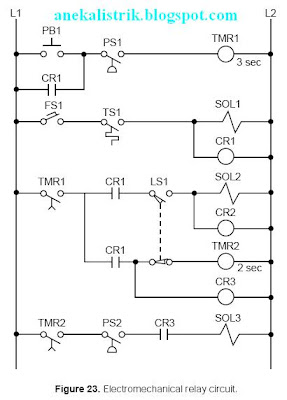
This relay replacement example involves the PLC implementation of the electromechanical circuit shown in Figure 23.
The hardware timer TMR1 requires instantaneous contacts in the first rung, which are used to latch the rung. If the instantaneous TMR1 contacts are implemented using a PLC timedelay contact, then PB1 must be pushed for the timer’s required time preset to latch the rung. This instantaneous contact will be implemented by trapping the timer with an internal output.

Tables 8 and 9 show the I/O address and internal output assignments for the electromechanical circuit’s real I/O. Table 10 presents the register assignment table. Note that internals do not replace control relays CR1 and CR2 since the output addresses 030 and 031 corresponding to solenoids SOL1 and SOL2 are available. Therefore, addresses 030 and 031 can replace the CR1 and CR2 contacts, respectively, everywhere they occur in the program. The normally open contact LS1 connects limit switch LS1 to the PLC input interface; and the normally open LS1 reference, programmed with an examine-OFF instruction, implements the normally closed LS1 in the program. Figure 24 illustrates the PLC program coding solution.


No comments:
Post a Comment